
This is a start to finish plan on how to use Azure Site Recovery (ASR) to protect your VMware and physical servers in the event of a disaster. You can protect far more than just VMware and physical servers with ASR but this is the most common scenario I encounter with customers and a straightforward place to begin.
Every infrastructure should have a business continuity and disaster recovery (BCDR) plan in place for times when there is an outage or worse when there is a disaster, natural or not. I have many customers who have DR site, meaning they have second data center that is a duplicate of all critical workloads hosted in their primary data center. As you can imagine, paying the bill for servers, cooling, floor space, racks, administration, electricity, so on that isn’t being used by the company to generate revenue, is never what your CIO wants to sign off on. But the alternative is to hope they never get phone call (assuming phones are up) from the CEO asking why those services are not up. I have been in the room when those phone calls take place and the usual reaction is shear panic. It is what we call a resume generating event for most CIO’s and likely one or more directors as well.

I will start with a simple conceptual design to explain how a typical design works to protect your infrastructure. Next, I will explain the logical design of a typical architecture. After the foundation has been established I explain the design principles and finally implementation. Along the way I will provide the details that lead to the design decisions I have chosen and possible alternative design decisions.
ASR supports two main orchestrated recovery scenarios. The first is orchestration of workload recovery between customer primary/secondary datacenters. The second is orchestration of workload recovery and migration between customer datacenter and Azure IaaS, or simply migration. In this disaster recovery scenario you will be launching your workload recovery in Azure IaaS only until you can resume operations on-premise.
This article is focused on the on-premise infrastructure. Using ASR to protect a mix of VMware servers and physical servers that also include physical storage. The concepts and methodologies here apply to workloads like SQL, Dynamics, protecting other platforms such as Hyper-V, VMM and Azure, the difference in these being the options available.
Other common scenarios ASR supports include: Replicate Active Directory and DNS, Protect SQL Server, Protect SharePoint, Protect Dynamics AX, Protect RDS, Protect Exchange, Protect SAP, Protect IIS, Protect Citrix XenApp and XenDesktop, Workload summary
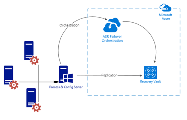
In this conceptual diagram, on the left is the on-premise infrastructure that has servers we want to protect. On the right is Azure. In the on-premise portion notice all the servers are sending traffic to the Process & Config server, this server is used to communicate with Azure. It handles a number of things but most important is that it replicates the changes on your servers to Azure keeping the two in sync. The red cog on each server is the Mobility Service, this is what actually tracks the changes on your servers and tells that to the Process & Config server. On the right side (secondary site) of the diagram you see just the Recovery Vault and ASR Failover Orchestration. The Process & Config server replicates the servers data to the Recovery Vault where it is stored. When a disaster occurs, the configuration stored in the Recovery Vault is what Azure will use to build the Azure VM’s to duplicate your on-premise servers. It is important to note that replication happens directly with Azure storage, the traffic is not processed by the Site Recovery service, only meta-data required to orchestrate replication and failover is sent to the Site Recovery service. And that is the final piece, listed below as the ASR Failover Orchestration. What isn’t shown below is the Azure storage (blob storage). Azure storage is part of your Recovery Vault and to keep this diagram simple I decided not to show the storage separately because it doesn’t actually go from the Recovery Vault to the blob storage.
If you were designing recovery for a publicly hosted workload the conceptual design and even the services would be different. Adding in Traffic Manager hosted in Azure would then give you the ability to failover from on-premise into Azure without having to make public DNS changes and waiting for them to propagate.
This second diagram is a logical depiction of the same workload recovery process. On the left is the on-premise infrastructure, the right is Azure. I won’t explain this here because it would be more depth than is really warranted but if you need to understand where specific services are in the stack or how Azure compares to the logical design of VMware this diagram is for you.

Capacity Planning
Capacity planning is critical for a successful solution to DR. Without the proper tools and guidance this would be a challenging task for most. As an example, to how things different compared to the DR solutions designed decades ago. Here is an example…Azure Site Recovery requires a storage account in Azure. The storage account is defined in the replication settings of your recovery plan. This means that any virtual machine migrated using a recovery plan will be placed in the same configured storage account.
Pay close attention to this paragraph. Storage accounts have limits, one for those is the total storage (500 TB) and maximum concurrent IOPS for a single storage account is 20,000 IOPs. A single disk can have up to 500 IOPs. So, the maximum number of VHDs that can be placed into a storage account is 40 assuming that the disks are all concurrently using the max IOPS. If the VHDs are using a lower average IOPs, then more VHDs can be in a single storage account. This refers to standard not premium storage.
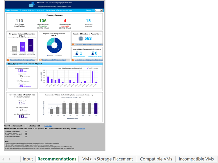
Instead of trying to calculate all of this thankfully you can instead just download the site recovery planning tool provided for free by Microsoft that will figure out all this and more for you. The details on how to use it are here. This tool needs to run for a couple weeks to collect data so you should download it now and get it collecting data.
There is also an equivalent tool for Hyper-V replication.
Capacity Planning continued
If the workloads you are protected are large enough you could be failing over more VMs than what is supported in a single storage account. If that is the case, you will need to automate the process of unprotecting the VMs, change their storage account and then apply protection to them again. You could also have a recovery plan call another recovery plan. Both of these scenarios are beyond the scope of this but it is important to understand the limits of storage accounts in Azure or your recovery could turn into a nightmare as you wait and wait for your now heavily throttled VHDs to boot. That tool will figure out where to place all the VHD’s to avoid this, automatically.
Prior to designing your recovery plan you should know how many storage accounts are required. This is based on the total size of all replicated data, the daily churn rate of your protected workload, and the days of retention. Essentially the total amount of storage (ts) that would be required after you have completed the initial replication to Azure, the amount of data that changes per day or churn rate (cr) times the number of days of retention (rd).
Or expressed simply as ts + (cr x rd). The problem with this calculation is it does not consider the IOPS limit of 20,000 per storage account. But you will also need to know what size VMs in Azure you will be running to really know what IOPS you will need for your storage account.
But there are other factors to consider when planning for scale and capacity of ASR. For instance, a Process server can only replicate a maximum of 2TB a day. A VM being replicated can only be assigned to a single Process server but more importantly is the sum of the daily churn of all VMs being replicated by the Process server that needs to be considered. You can add additional process servers to handle more than 2TB of churn per day…
Azure Site Recovery services requires that a Site Recovery Vault is created. The vault contains the Azure Site Recovery settings, the certificate and the vault key. The certificate is used as part of the data encryption process and must be created and uploaded into the vault. The vault key is used to allow communication from the provider to the vault. This is depicted in the logical diagram above.
If you read all of this after the note about the free tool that does a better job than I can in Excel, kudos. There is some important information in the previous paragraphs.

Carefully consider growth factor
Let’s assume we ran the tool for more than two weeks and have great data. We know have a really good idea on our capacity, we have the number of storage accounts we will need, the number of Azure cores required for a failover (and we won’t exceed them), we know where are VM storage placement is going to be, what VM’s are not compatible and why, we know how long the
initial replication into Azure will take, our daily churn rate, we have factored in our growth, we even did what-if analysis.
To Do’s:
Download the site recovery planning tool and run it!
Carefully consider growth factor
VM’s are not compatible and why
Review prerequisites for VMware replication
To begin planning your recovery you first need to determine if your failover requires your severs to maintain their same IP address. Since most of what you would failover in this scenario does require static IP addresses that means you will also need to failover your subnet as part of the recovery plan. Because Azure does not support stretch networking and because these are not externally facing workloads you will need to have a network connection between Azure and your on-premise data center for the services to be accessible. This can be in the form a VPN connection or ExpressRoute connection. You can even automate the building of your VPN connection as part of your recovery plan.

Review the prerequisites for VMware to Azure replication
‘Azure virtual networks define the network connectivity within Azure datacenters, between Azure datacenters, and between Azure datacenters and on-premises datacenters. It is possible to configure Azure virtual networks to be isolated or to be connected to other virtual networks and allow traffic to route between the virtual networks.
Each virtual network definition has an address space pool and one or more subnets. Subnets should be defined within the virtual network prior to placing any virtual machines. Once a subnet has an IP Address in use, it cannot be modified without removing all devices using IP addresses.’
With the limitation of 2048 VMs per virtual network in Azure, a class B subnet is used, a subnet mask of 255.255.248.0 or /21 is the largest range of addresses that should be assigned without wasting addresses.
When you create a VM in Azure you must also deploy that VM to a Vnet with a subnet. You can no longer deploy a VM without a subnet like you could with Azure classic (ASM). That means in order to have a connection to your on-premise data center with a network IP range that matches your on-premise network those two should never talk.
In this diagram, I show how to accomplish this. On the left, again is your on-premise datacenter, on the right is Azure. We are going to failover the server within the 192.168.1.0/24 subnet, and because it has a static IP, when it comes up in Azure it needs to have that same IP and come up on that same subnet, called our recovery network.
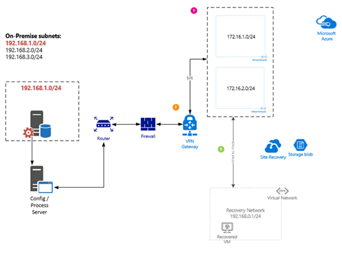
What is going to happen in this scenario is we are going to automate the building of the VPN connection using an runbook, the building of two additional VNets in Azure, and then the Vnet-to-Vnet connection between our recovery network and the new VNets, the 172.16.x.x Vnet that contains the two subnets. This will all be automated in our recovery plan, but if you wanted to use a persistent connection or needed to for other Azure services between your on-premise data center and Azure then you would have the additional VNets already in Azure (most likely) and then you would just automate the Vnet-to-Vnet connection so that it was not visible until you were failing over to Azure.
During the failover the router will programmatically failover the entire subnet from your on-premise network. Pay close attention to that statement, it means anything on that subnet will need to be included in your recovery plan or when your recovery plan runs any on-premise assets on that subnet will lose their network connection to that subnet. It also means that you will most likely need to make updates to routes as part of this process. The automated migration of the subnet and updating of routes is specific to your networking equipment and can’t be covered here.
Here are the steps you would need to follow to complete this scenario.
Steps required prior to any failover
- Creation of the Azure Virtual network that will act as the recovery network (192.168.1.0/24 in the diagram above). This is done much later in the process.
- Configure the VM properties by specifying the static IP address being used on-premise.
 Steps required during a failover
Azure Vnet network and subnets need to be deployed (172.16.1.0/24 and 172.16.2.0/24 in the diagram above).
 Alternatively, these could be deployed prior to a failover as part of the ASR setup.
VPN Site-to-Site (S2S) connection is required to be in place connecting on-premise and Azure networks.
 It is important to note that creating the VPN Gateway device in Azure can take ~45 minutes, I just deployed one and it took 25 minutes. Depeding on your RPO, this may by acceptable.
Vnet to Vnet connection between Azure Networks.
- After documenting, all of this and going through all of the steps. There are two issues with these previous steps. (1) The Recovery network is required at the time replication is enabled on protected systems. (2) Taking 25-45 minutes for the gateway to become available is going to be a problem for most people when they are planning for DR. As of today there is no way to simply shutdown a gateway device, you can delete one but it isn’t possible to turn it on configure it, and then turn it back off. If a customer already has VPN or ER or ER+VPN into Azure it isn’t going to impact them but other customers who host everything in Azure with only some on-premise or the other way around it complicates the decision.
To Do’s:
Identify and list your subnets to be failed over from production to Azure
List of static IP addresses for servers being protected by ASR
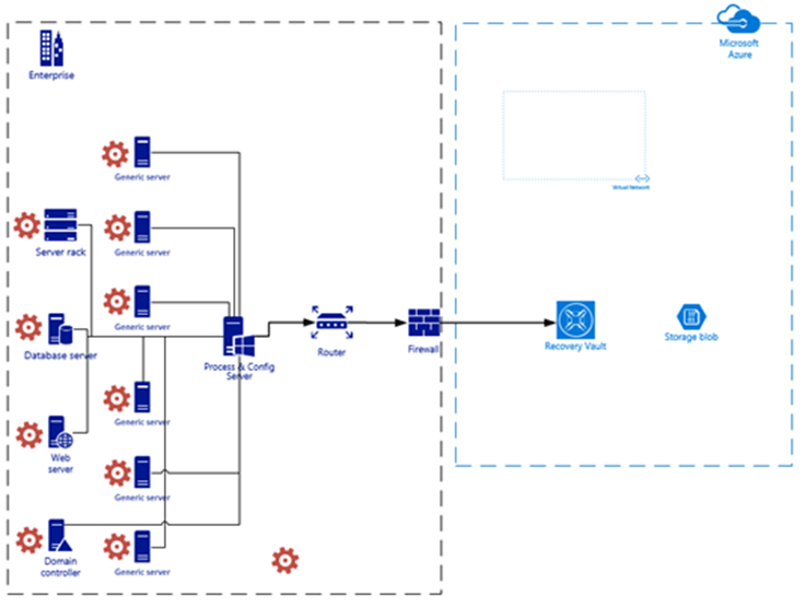
The image below is an example of a high-level architecture of ASR. The left side represents the on-premise enterprise or on-premise portion and Azure is on the right-side. Worth noting is the location of the Process & Config server and that each server being protected by ASR has the Mobility Service installed. In Azure the recovery network is included as well as the blob storage where the replicated data is stored. If you go back to the concept diagram neither the blob storage or VNet (recovery network) are shown. That was intentional but they are shown here since they have been covered in the previous topics.
Recovery Vault Setup
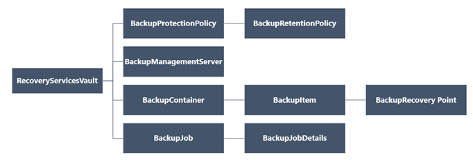
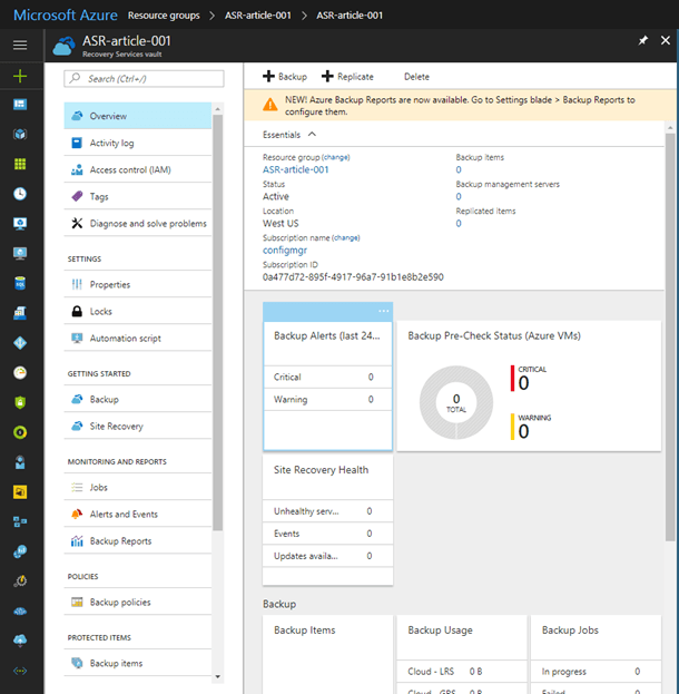
Before you can configure Azure or on-premise the Recovery Vault must be created in Azure. As you can see here even for backups everything relies on the Recovery Services Vault (Recovery Vault or vault).

Creating a Recovery Services Vault
The simplest way to create one would be with New-AzureRmRecoveryServicesVault. But, since we are going to reply on this for recovery we should plan and execute carefully so we will step through the configuration instead.
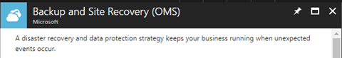
Assuming you do not already have a Recovery Services Vault already in Azure. Finding where to create one can be tricky, it is actually part of OMS, both ASR and Azure Backup are part of OMS. What I found easiest is to just type “Recovery Services” in the search bar, and it is the first one. “Backup and Site Recovery (OMS)”
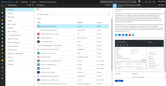
If you are ready to create the Recovery Vault, click on Create.
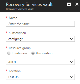
This just takes you to a new set of blades to fill out the required parameters. You should already know where, geographically, you want your recovery vault based on the 2 week plus analysis. I haven’t talked about naming conventions in Azure but I have an entire presentation on how to do this in Azure, and how not to do it, which is what usually happens. If you have an established naming convention in Azure, and it is well thought out, use it. This isn’t your typical resource group that you are creating so there is some latitude for being creative should you not yet have a standard. Once you are happy with all the fields click the Create button and off we go.
Technically this is the Recovery Vault, which is almost all the settings, configuration and management of both ASR and Azure Backup. That little icon in the diagram doesn’t really do it justice.
Before we switch gears and move to the on-premise setup we need to do a few small things first.
Download our Config & Process server software, and the vault registration to go with it. And then make sure we have at least one storage account and Vnet (we will do the Vnet later).
In the Azure console:
- Click Recovery Services vaults > vault.
- In the Resource Menu, click Site Recovery > Prepare Infrastructure > Protection goal.
- In Protection goal, select To Azure > Yes, with VMware vSphere Hypervisor.
- Click > Source
- Then click the plus next to Configuration Server to open the final blade where the link is to download the Config & Process server software.
- On the Add Server blade, download the Config & Process server software (3.), and also download the vault registration key (4.), we will need it so don’t forget where it saves to.
Now we move temporarily to on-premise setup.
This involves:
- Installing and setting up the Config & Process server
- Preparing VMware for discovery and communication with ASR
- Preparing for and deploying the Mobility Service
Verify the hardware prerequisites for the Config & Process server
To install the Config & Process server you must also have a VMware VM ready and an account with the proper rights in VMware for discovery.

How to influence the bandwidth on your process server consumes
Installing the Config & Process server
Config & Process server minimum requirements
To install the Config & Process server, on the VMware VM you created, copy the unified installer for Azure Site Recovery that we downloaded from the Azure console.
- On the configuration server VM, make sure that the system clock is synchronized with a Time Server. It should match. If it’s 15 minutes in front or behind, setup might fail.
- Run setup as a Local Administrator on the configuration server VM.
- Make sure TLS 1.0 is enabled on the VM.
After you launch the installer there are server clicks of the Next button which you can manage without my witty banter.
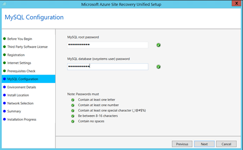
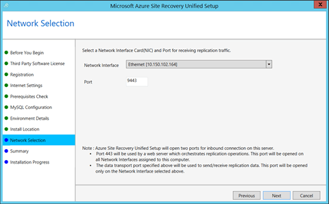
(This is a condensed version of the number the dialog boxes)
Preparing VMware
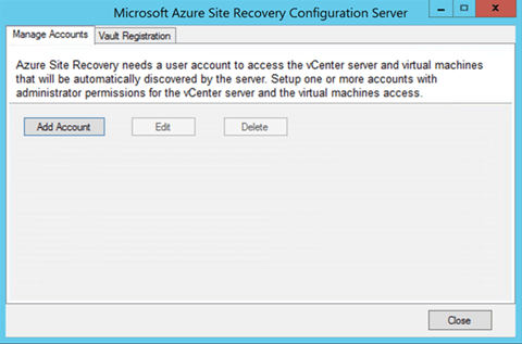
To prepare on-premises VMware servers to interact with Azure Site Recovery, and prepare VMware VMs for the installation of the Mobility service two accounts are required.
- Account for automatic discovery of VMware VMs
- Account for the push installation of the Mobility Service
First up, Add the VMware account for automatic discovery
Once the Config & Process server install is completed, you will see CSPSConfigtool.exe on the desktop of the server.
Launch that to setup the account for communication between VMware and ASR.
Click Manage Accounts > Add Account.
In Account Details, add the account that will be used for automatic discovery.
Site Recovery automatically discovers VMs located on vSphere ESXi hosts, and/or managed by vCenter servers. To do this, Site Recovery needs credentials that can access vCenter servers and vSphere ESXi hosts. Create those as follows:
- To use a dedicated account, create a role (at the vCenter level, with the permissions described here. Give it a name such as Azure_Site_Recovery.
- Then, create a user on the vSphere host/vCenter server, and assign the role to the user. You specify this user account during Site Recovery deployment.
Mobility Service Install
Prepare an account to install the Mobility service agent on VMs.
The Mobility Service must be installed on all VMs you want to replicate. There are a number of ways to install the service, including manual installation, push installation from the Site Recovery process server, and installation using methods such as System Center Configuration Manager.
Each installation method follows their own set of rules so I have included links to all of them so you don’t get stuck here.
Install Mobility Service by using software deployment tools like System Center Configuration Manager
Install Mobility Service by using Azure Automation and Desired State Configuration (Automation DSC)
Install Mobility Service manually by using the graphical user interface (GUI)
Install Mobility Service manually at a command prompt
Install Mobility Service by push installation from Azure Site Recovery
The setup logs can be found under %ProgramData%\ASRSetupLogs\ASRUnifiedAgentInstaller.log
The AgentConfiguration logs can be found under %ProgramData%\ASRSetupLogs\ASRUnifiedAgentConfigurator.log
If you want to use push installation, you need to prepare an account that Site Recovery can use to access the VMs.
- You can use a domain or local account
- For Windows, if you’re not using a domain account, you need to disable Remote User Access control on the local machine.
To do this, in the register under HKEY_LOCAL_MACHINE\SOFTWARE\Microsoft\Windows\CurrentVersion\Policies\System, add the DWORD entry LocalAccountTokenFilterPolicy, with a value of 1.
That’s it for on-premise setup! There isn’t much to it except installing the server.
Enabling Replication for VMware in Azure
Ground rules
- VMware VMs must have the Mobility service component installed. – If a VM is prepared for push installation, the process server automatically installs the Mobility service when you enable replication.
- Your Azure user account needs specific permissions to enable replication of a VM to Azure
- When you add or modify VMs, it can take up to 15 minutes or longer for changes to take effect, and for them to appear in the portal.
- You can check the last discovered time for VMs in Configuration Servers > Last Contact At.
- To add VMs without waiting for the scheduled discovery, highlight the configuration server (don’t click it), and click Refresh.
- By default all disks on a machine are replicated. You can exclude disks from replication. For example you might not want to replicate disks with temporary data, or data that’s refreshed each time a machine or application restarts (for example pagefile.sys or SQL Server tempdb). When you add a machine to a replication plan you have to specify the OS disk, and can then choose which disks you want to include in the replication. Learn more
And we still need to create the recovery network. This is the Vnet that will get all the VM’s deployed to it during failover and is required when we enable replication.
This creates the recovery (failover) Vnet with a single subnet. It also creates the External facing Vnet with a subnet. The critical portion of this setup is that the Vnet peering is not setup so that the recovery network does not connect over VPN or ExpressRoute to the on-premise network. This could cause an outage on its own if it were to happen.
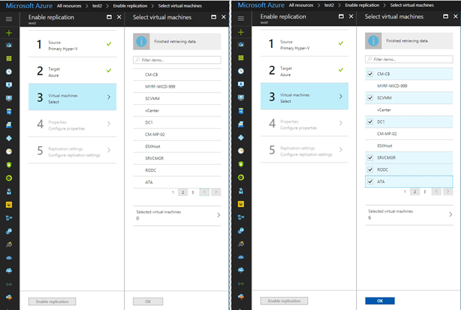
As part of the Recovery Vault setup, protected items are configured. Adding a protected item in the vault allows you to establish a connection to the ASR Configuration & Process server. Once the connection is established, and the Mobility Service is deployed on all targeted systems, you can select individual servers to enable for protection. You can see here I have a system called DC2 that is failing to replicate and a number of other systems that the protection has just been enabled on. Until the service is installed on each VMware VM you will not see them listed in the Azure portal.
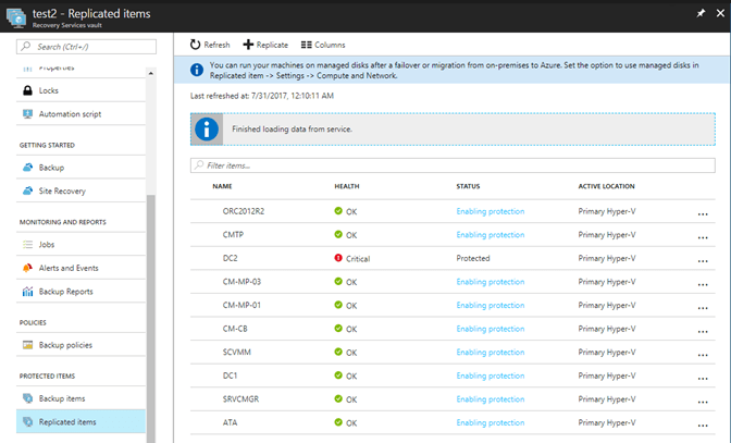
Once protection is enabled, the encryption and replication of the contents of the hard drives begin and is eventually copied from the Process & Config server to the storage account in the vault. Once the initial replication of the protected systems hard drives has occurred, they can be added to a recovery plan.
But before we get too deep into recovery we first need to cover replication, recovery does us no good without the data.

How to influence the bandwidth on your process server consumes
It is important to plan and execute when dealing with important things. Protecting your employer’s data is paramount and just as important is protecting their critical services. That means before you begin making replication policies you plan them out. Only after all stakeholders have signed off on the plan, can you then execute on that plan by creating the policies.
When crafting replication policies, these will depend on the workloads and how important their data is. SAP, Salesforce, those types, you cannot afford to lose the data in these systems without losing revenue. Your Configmgr server, well if you built your architecture like myself, other MVP’s, and Microsoft recommended, then it can be down for quite a while, possibly even more than a day before anyone even notices, even longer before problems really start. Keep in mind this is not your recovery plan, this is separate so the choices you make for replication are independent (to a point) from failover and recovery. It would be best to review you current replication policies and see if they need to be revised based on changes since they were created back in the 90’s. If you decide to review them or not when you create the policies in ASR it should already be planned out and just a matter of filling in the boxes. Don’t just wing it, this is someone’s data and likely somehow impacts revenue.
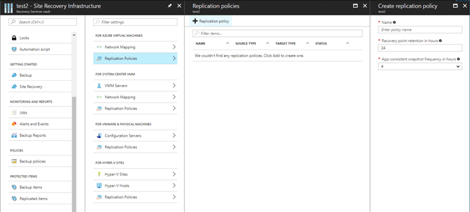
The basic replication policy has three settings, name, recovery point retention and app-consistent snapshot frequency.

The frequency of replication will depend on the type of systems being replicated.
For VMware and physical server replication frequency is not relevant as it continuously replicates changes.
SAN replication is synchronous and for Hyper-V replication VMs can be replicated every 30 seconds, 5 minutes, or 15 minutes.
You can of course, have multiple replication plans. And even though replication may be enabled, plans in place and systems talking with ASR, until you add them to a replication plan, they are not replicating their data.
Staggering systems is a common tactic for the initial replication to control the amount of data, time of day, and to get the highest priority workloads protected first.
To create a Replication Plan
To create a new replication policy, in the Azure console
- Click Site Recovery infrastructure > Replication Policies > +Replication Policy.
- In Create replication policy, specify a policy name.
-
In RPO threshold, specify the RPO limit. This value specifies how often data recovery points are created. An alert is generated if continuous replication exceeds this limit.

- In Recovery point retention, specify (in hours) how long the retention window is for each recovery point. Replicated VMs can be recovered to any point in a window. Up to 24 hours retention is supported for machines replicated to premium storage, and 72 hours for standard storage.
- In App-consistent snapshot frequency, specify how often (in minutes) recovery points containing application-consistent snapshots will be created.
-
Click OK to create the policy.
Questions about security, encryption, compliance?
Adding Systems to your Replication Plan
After you have created the replication policy rules, you can select VMs to add to the policy.
- Select “3. Virtual Machines” and then from the blade choose each VM you want to add. They are displayed 10 at a time so you can browse the pages of VMs or use the search bar.
- Simply select the box next to the VM to add it.
-
When you are done selecting the VMs click the OK button.
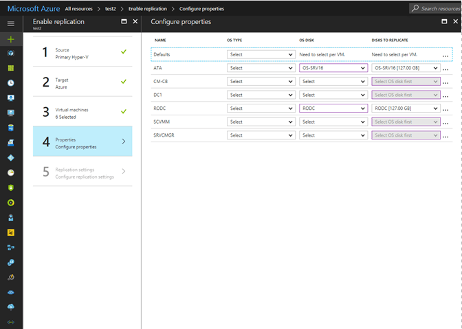
When you add a VM to the replication policy you must then specify which OS type, Windows or Linux, and then from the list of drives specify which drive is the OS disk. It will do its best to guess which one is the correct one but you have to have one selected for each VM to proceed.
The far-right column, Disks To Replicate, this is where you can choose which disks you want to include in replication. I mentioned earlier you could exclude disks that didn’t need to be replicated, and this is where you configure that.
Keep in mind that a VM can have only one replication policy. So, you may need to craft a special policy for that one system, or that one workload but if you do not choose to include one of its disks here, it will not be replicated as part of another policy since a system can only be in one replication policy.
Now that we have replication working, we can take advantage of the time it takes for the initial replication to complete to prepare for and build our recovery plans.
Setting Static IPs
In most cases, and in ours, we require our systems on-premise to have a static IP and when the recovered system runs in Azure we need it to have the same static IP address on the same subnet as if nothing has happened. After a protected system has finished its initial replication we can configure these settings.
To configure a static IP for a protected system, in the Azure console, open the Recovery Services vault.
-
Click Replicated Items > Select the name of the system you wish to configure. Create Recovery Plan.
-
Click Compute and Network on the replicated items Settings blade.
-
On the Compute and Network blade under the Network Properties select the appropriate Target Network > Target Subnet and then enter the static IP address in the Target IP field. When you are finished click Save.
-


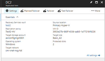

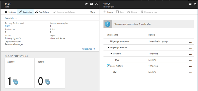
A recovery plan allows you to establish a grouping of protected VMs/workloads. All the VMs within the recovery plan are failed over as a unit during a disaster recovery situation. Within the recovery plan you can create one or more groups of VMs to control the startup process when the failover occurs. Here you can see I am going to add the same VM DC2 to a recovery plan.
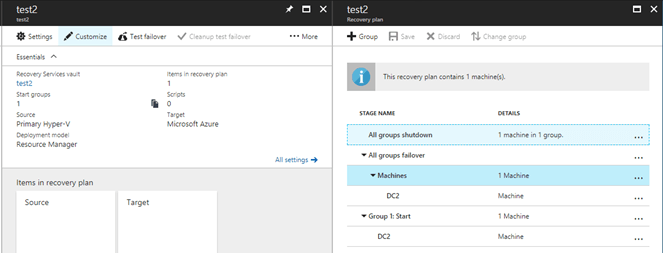
Once I have my protected items added to my recovery plan and create the recovery plan I can then customize the recovery plan such as grouping VMs. Here you can see the right blade has the group button.
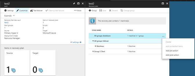
There is actually four different customizations you can make to the recovery plans and there are options to run any of them before a group begins as well as after a group has finished.
Add new groups – allows you to add recovery plan groups to the current one.
Add a manual action – This actually pauses the failover for a manual action you may need to take or wait to complete.
Add a script – This allows you to run a script before and after each group.
Add Azure runbooks – This allows you to extend recovery plans to do almost anything you need. Automate tasks, create single step recovery, failback, check for flooding before continuing. Almost limitless. I will actually use this to achieve quite a bit of automation during a failover.
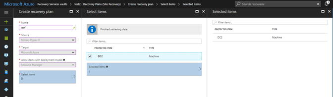
To create a recovery plan, in the Azure Console.
-
Click Recovery Plans > Create Recovery Plan. Specify a name for the recovery plan, and a source and target. The source location must have virtual machines that are enabled for failover and recovery.
For a VMware VM or a physical on-premises server to Azure, select a configuration server as the source, and Azure as the target.
-
In Select virtual machines, select the virtual machines (or replication group) that you want to add to the default group (Group 1) in the recovery plan.
A this point you can customize the recovery plan using groups and the four additional customizations discussed above.
Achieving Faster Recovery Times Using Runbooks and Workflows
Back in the Networking section I discussed the process of failing over an entire subnet during a disaster. I also listed several other requirements to be automated for a successful recovery. To achieve success, we could do all the steps manually, document each step of each task and hope the process was still the same when we actually needed to go through it, or we could automate them and include them as part of our recovery plan.
In this section I am going to briefly talk about Azure Automation and describe what we need to achieve and then demonstrate how easy it can be to automate these complex and inter-connected processes.
The automation of this process is actually quite extensive and requires additional details to make it usable. At its highest level there are 8 steps in the process that have to be automated for a successful recovery.
- Two VNets, each with a subnet, is created.
- The peering between the new VNets is created.
- The gateway subnet for the VPN connection on the external Vnet is created.
- The local gateway connection and configuration for the VPN tunnel is created.
- A request for a public IP address for the VPN GW is completed.
- The VPN GW IP addressing configuration is created.
- Then the VPN GW is built (this can take 45 mins)
- The on-premise VPN device needs to be configured.
- Then finally, the VPN connection between the Azure and the on-premise VPN device is established.
In the process of writing this I have discovered that my original idea didn’t quite fit as I had hoped, but for the purpose of showing off the power of PowerShell runbooks we will stick with the original “requirements” listed above.

Make sure your VPN device is compatible
Before we add the runbooks to our recovery plan they first have to exist in Azure Automation. If you haven’t used Azure Automation yet you will need to set it up and specifically the automation account created.

Once you have Azure Automation setup and working you will also need to add PowerShell modules to your automation account. The runbooks will not work without them, it is similar to not have PowerShell modules installed on your server or work computer. If you are using a new automation account and have already added the modules to your subscription you do not need to add them again, they are installed per subscription.
If you do know how to use Azure Automation you may wonder why I don’t just use a PowerShell Workflow instead? The advantages to using a workflow over a runbook seem to make sense. I won’t get into the details of why here, but I wasn’t going to use parallel processing, we need these to run in serial, and the checkpoint doesn’t really buy us much here. Since they scripts are small the PowerShell runbook should complete faster as it doesn’t have to be compiled like the workflows does, and speed is really what we are after. There is an outage after all.
As much as I would like to spend a lot of time on automation this is already lengthy enough so I won’t walk through the process of creating each runbook, testing it, and publishing it. If you are new to runbooks in Azure here is a great short walkthrough on creating your first Azure PowerShell runbook that explains it well enough to reuse my runbooks.
In each recovery plan we can use Azure Automation, we can inject a pre or post action between each group in the recovery plan. Allowing us to literally run code before any other action is carried out by the recovery plan, and running codes as the last action in the recovery plan. And of course, in between those two points. I will choose to insert a pre-action at the start that will then kick of a runbook I have stored in my Azure Automation library.
When you select which type of action you want to run you are presented with the insert action blade where you can choose which runbook you want to run.
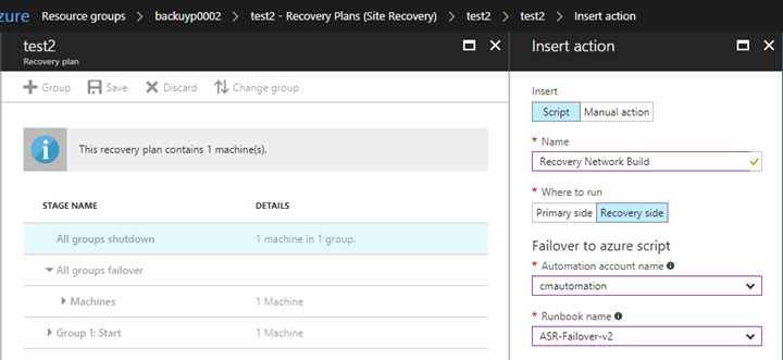
The recovery side is Azure in this case, since it is where the recovery is taking place. You must use the correct automation account to be able to see and run the runbook, for security reasons. And that is all you must do. The code to complete all the original tasks is in the block below. It could (should) be broken up into distinct runbooks instead of being combined but I didn’t think I would even get the time to build more than a couple commands. Enjoy.
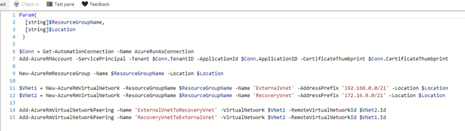
Param(
[Parameter(Mandatory = $true)]
[string]$ResourceGroupName,
[Parameter(Mandatory = $true)]
[string]$Location = ‘westus’,
[Parameter(Mandatory = $true)]
[string]$SharedKey = ‘!k$x0VEZwy8&UQ9wO’,
[Parameter(Mandatory = $false)]
[string]$DnsServer,
[Parameter(Mandatory = $false)]
[string]$ExtVnetName = ‘ExternalVnet’,
[Parameter(Mandatory = $false)]
[string]$RecVentName = ‘RecoveryVnet’,
[Parameter(Mandatory = $true)]
[string]$VPNDeviceIP
)
# Authenticate to Azure AD
$Conn = Get-AutomationConnection -Name AzureRunAsConnection
Add-AzureRMAccount -ServicePrincipal -Tenant $Conn.TenantID -ApplicationId $Conn.ApplicationID -CertificateThumbprint $Conn.CertificateThumbprint
# Subnets for each net VNet
$ExternalSubnet = New-AzureRmVirtualNetworkSubnetConfig -Name ExternalSubnet -AddressPrefix “192.168.1.0/24”
$RecoverySubnet = New-AzureRmVirtualNetworkSubnetConfig -Name RecoverySubnet -AddressPrefix “172.16.1.0/24”
New-AzureRmResourceGroup -Name $ResourceGroupName -Location $Location
# Create new VNets -DnsServer $DnsServer
$VNet1 = New-AzureRmVirtualNetwork -ResourceGroupName $ResourceGroupName -Name ‘ExternalVnet’ -AddressPrefix ‘192.168.0.0/21’ -Location $Location -Subnet $ExternalSubnet
$VNet2 = New-AzureRmVirtualNetwork -ResourceGroupName $ResourceGroupName -Name ‘RecoveryVnet’ -AddressPrefix ‘172.16.0.0/21’ -Location $Location -Subnet $RecoverySubnet
# Create Vnet-to-Vnet Peering between new VNets
Add-AzureRmVirtualNetworkPeering -Name ‘ExternalVnetToRecoveryVnet’ -VirtualNetwork $VNet1 -RemoteVirtualNetworkId $VNet2.Id
Add-AzureRmVirtualNetworkPeering -Name ‘RecoveryVnetToExternalVnet’ -VirtualNetwork $VNet2 -RemoteVirtualNetworkId $VNet1.Id
# Create Gateway subnet for VPN connection on ExternalVnet
Add-AzureRmVirtualNetworkSubnetConfig -Name ‘GatewaySubnet’ -AddressPrefix ‘192.168.4.0/27’ -VirtualNetwork $VNet1
Set-AzureRmVirtualNetwork -VirtualNetwork $VNet1
# Create local (on-premise) gateway connection with multiple on-premise address prefixes
New-AzureRmLocalNetworkGateway -Name LocalSite -ResourceGroupName $ResourceGroupName -Location $Location -GatewayIpAddress $VPNDeviceIP -AddressPrefix @(‘10.0.0.0/24′,’20.0.0.0/24’)
# Request the PIP address for the VPN gateway
$GWPIP = New-AzureRmPublicIpAddress -Name GWPIP -ResourceGroupName $ResourceGroupName -Location $Location -AllocationMethod Dynamic
# Set VPN Gateway IP addressing configuration
$VNetVPN = Get-AzureRmVirtualNetwork -Name $ExtVnetName -ResourceGroupName $ResourceGroupName
$SubnetVPN = Get-AzureRmVirtualNetworkSubnetConfig -Name ‘GatewaySubnet’ -VirtualNetwork $VNetVPN
$GwIpConfig = New-AzureRmVirtualNetworkGatewayIpConfig -Name ‘GwIpConfig’ -SubnetId $SubnetVPN.Id -PublicIpAddressId $GWPIP.Id
# Create VPN Gateway
New-AzureRmVirtualNetworkGateway -Name ‘VNetGW’ -ResourceGroupName $ResourceGroupName -Location $Location -IpConfigurations $GwIpConfig -GatewayType VPN -VpnType RouteBased -GatewaySku VPNGW1
# Configure on-premise VPN device
# Shared key, PIP of GW
# Create VPN Connection – Set variables
$Gateway = Get-AzureRmVirtualNetworkGateway -Name ‘VNetGW’ -ResourceGroupName $ResourceGroupName
$Local = Get-AzureRmLocalNetworkGateway -Name LocalSite -ResourceGroupName $ResourceGroupName
# Create VPN Connection
New-AzureRmVirtualNetworkGatewayConnection -Name ‘ExtGWConnection’ -ResourceGroupName $ResourceGroupName -Location $Location -VirtualNetworkGateway1 $Gateway -LocalNetworkGateway2 $Local -ConnectionType IPsec -RoutingWeight 10 -SharedKey $SharedKey
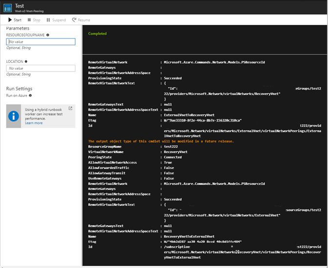
As for the runbooks here is an example of the runbook I created in Azure that creates the two VNets and the peering between them.
When I run a test on in in the portal you can see it works. Notice on the left there are parameters to enter. These are based on the parameters specified in the runbook in the first few lines.
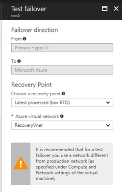
It is recommended that when you are doing a test failover you choose a network that is isolated from your production recovery site network that you provided in Compute and Network settings for the virtual machine. By default when you create an Azure virtual network, it is isolated from other networks. This network should mimic your production network:
-
Test network should have same number of subnets as that in your production network and with the same name as those of the subnets in your production network.
-
Test network should use the same IP range as that of your production network.
-
Update the DNS of the Test Network as the IP that you gave as target IP for the DNS virtual machine under Compute and Network settings. Go through test failover considerations for active directory section for more details.
 Prepare to connect to Azure VMs after failover
Running the test failover
-
Select Recovery Plans > test2
. Click Test Failover.
-
Select a Recovery Point to failover to. You can use one of the following options:
-
Latest processed: This option fails over all virtual machines of the recovery plan to the latest recovery point that has already been processed by Site Recovery service. When you are doing test failover of a virtual machine, time stamp of the latest processed recovery point is also shown. If you are doing failover of a recovery plan, you can go to individual virtual machine and look at Latest Recovery Points tile to get this information. As no time is spent to process the unprocessed data, this option provides a low RTO (Recovery Time Objective) failover option.
-
Latest app-consistent: This option fails over all virtual machines of the recovery plan to the latest application consistent recovery point that has already been processed by Site Recovery service. When you are doing test failover of a virtual machine, time stamp of the latest app-consistent recovery point is also shown. If you are doing failover of a recovery plan, you can go to individual virtual machine and look at Latest Recovery Points tile to get this information.
-
Latest: This option first processes all the data that has been sent to Site Recovery service to create a recovery point for each virtual machine before failing them over to it. This option provides the lowest RPO (Recovery Point Objective) as the virtual machine created after failover will have all the data that has been replicated to Site Recovery service when the failover was triggered.
-
Latest multi-VM processed: This option is only available for recovery plans that have at least one virtual machine with multi-VM consistency ON. Virtual machines that are part of a replication group failover to the latest common multi-VM consistent recovery point. Other virtual machines failover to their latest processed recovery point.
-
Latest multi-VM app-consistent: This option is only available for recovery plans that have at least one virtual machine with multi-VM consistency ON. Virtual machines that are part of a replication group failover to the latest common multi-VM application-consistent recovery point. Other virtual machines failover to their latest application-consistent recovery point.
-
Custom: If you are doing test failover of a virtual machine, then you can use this option to failover to a particular recovery point.
-
-
-
Select an Azure virtual network: Provide an Azure virtual network where the test virtual machines would be created. Site Recovery attempts to create test virtual machines in a subnet of same name and using the same IP as that provided in Compute and Network settings of the virtual machine. If subnet of same name is not available in the Azure virtual network provided for test failover, then test virtual machine is created in the first subnet alphabetically. If same IP is not available in the subnet, then virtual machine gets another IP address available in the subnet. Read this section for more details
-
If you’re failing over to Azure and data encryption is enabled, in Encryption Key select the certificate that was issued when you enabled data encryption during Provider installation. You can ignore this step if you have not enabled encryption on the virtual machine.
-
Track failover progress on the Jobs tab. You should be able to see the test replica machine in the Azure portal.
-
To initiate an RDP connection on the virtual machine, you will need to add a public ip on the network interface of the failed over virtual machine. If you are failing over to a Classic virtual machine, then you need to add an endpoint on port 3389
-
Once you’re done, click Cleanup test failover on the recovery plan. In Notes record and save any observations associated with the test failover. This deletes the virtual machines that were created during test failover.
This is a compiled list of prerequisites listed throughout the document. I didn’t feel like I did a good making them known in some parts so I wanted to put them all in a single place to hopefully make finding them easier.
Review the prerequisites for VMware to Azure replication
Prepare and account ot install the Mobility service agent on VMs
VM’s are not compatible and why
Config & Process server minimum requirements
Your Azure user account needs specific permissions to enable replication of a VM to Azure
To install the Config & Process server you must also have a VMware VM ready and an account with the proper rights in VMware for discovery.
Make sure your VPN device is compatible
This is like the prerequisites section above. I wanted to capture all of the To-Do’s in one place so they were easier to find and utilize.
Download the site recovery planning tool and run it!
Carefully consider growth factor
VM’s are not compatible and why
Identify and list your subnets to be failed over from production to Azure
List of static IP addresses for servers being protected by ASR

![Administrator: usage for SCAP 1.2: ScapToDcm. exe -scap ScapDataStreamFi1e [ -out OutputDirectory] [-select ScapDataStreamID/XccdfBenchma rkID/XccdfProfi1eID] [ -log LogFi1eName] [ -batch 588] Usage for SCAP 1.1/1. ø: ScapToDcm.exe -xccdf XccdfFi1e -cpe CPEFi1e [ -out OutputDirectory] [-select XccdfBenchmarkID/Xcc dfProfi1eID] [ -log LogFi1eName] [ -batch 588] Usage for OVAL: ScapToDcm.exe -oval OvalFi1e [ -variable OvalExterna1Variab1eFi1e] [ -out OutputDirectory] [ -log LogFi1eNa e] [ -batch 588] H: \Program Files (x86)\SCAP Extensions>scaptodcm.exe -xccdf . \ 2812\U R2 MS V2R6_STIG SCAP_1-1_Benc hmark-xccdf .xml -cpe . R2 MS V2R6_STIG_SCAP_1-1_Benchmark-cpe-dictionary.xm1 -out . \ 2812 Try to create log file: H: \Program Files (x86)\SCAP Extensions\ScapToDcm. log alidate the schema of XCCDF file H: \Program Files (x86)\SCAP MS V2R6 STIG SC P 1-1 Benchmark-xccdf .xml Successfully validate the schema of XCCDF file H: \Program Files (x86)\SCAP R2 MS V2R6 STIG SCAP 1-1 Benchmark-xccdf .xml Process XCCDF benchmark in file H: \Program Files Windows _ 2812 _ and _ 2812 R2 ms V2R6 STIG SCA? 1-1 Benchmark-xccdf .xml Process Process Process Process Process Process Process Process Process Process Process Process XCCDF XCCDF XCCDF XCCDF XCCDF XCCDF XCCDF XCCDF XCCDF XCCDF XCCDF XCCDF Benchmark Windows 2812 ms STIG Profile: Profile: Profile: Profile: Profile: Profile: Profile: Profile: Profile: Profile: Profile: MAC MAC- 1 MAC- 1 MAC- 2 MAC- 2 MAC- 2 MAC- 3 MAC- 3 MAC- 3 Classified-l - mission Critical Classified Public- I - mission Critical Public Sensitive- I - mission Critical Sensitive Classified-ll - mission Support Classified Public- II - mission Support Public Sensitive- II - mission Support Sensitive Classified-lll - Administrative Classified Public- III - Administrative Public Sensitive- III - Administrative Sensitive Disable Slow Rules-Disab1e Slow Rules 1 only Load file H: \Program Files Windows _ 2812 _ and _ 2812 R2 ms V2R6 STIG 1 for check content U Windows 2812 and 2812 R2 MS V2R6 STIG SCAP 1-1 Benchmark-oval .xml Process OVAL definitions in file H: \Program Files (x86)\SCAP R2 MS V2R6 STIG SC P 1-1 Benchmark-oval .xml Process OVAL: U Windows 2812 and 2812 R2 ms V2R6 STIG SCA? 1-1 Benchmark-oval .xml Successfully finished process OVAL: U R2 MS V2R6_STIG_SCAP_1-1_Benchmark-ova1 .xml Process CPE dictionary in file H: \Program Files (x86)\SCAP R2 MS V2R6 STIG SCAP 1 -1_Benchmark- cpe- dictionary . xml Load file H: \Program Files (x86)\SCAP R2 MS V2R6_STIG_SCAP_1-1_Benchmark-cpe-ova l.xml for check content R2 MS V2R6_STIG_SCAP_1-1_Benchmark-cpe-ova1 .xml Process OVAL definitions in file H: \Program Files (x86)\SCAP R2 MS V2R6 STIG SC P_l -1_Benchmark- cpe-oval . xml Process OVAL: U Windows _ 2812 _ and _ 2812 R2 ms .xml Successfully finished process OVAL: U R2 MS V2R6 STIG SCAP_1-1_Benchmark-cpe-ova1 .xml CCDF Benchmark: [Windows _ 2812 ms STIG] Version : update: Timestamp : Status: Status date: Title: Description : [2] [1/1/8881] [accepted] [18/28/2816] [Windows Server 2812 / 2812 R2 member Server Security Technical Implementation Guide] [The Windows Server 2812 / 2812 R2 member Server Security Technical Implementation Guide (STIG) is publ ished as a tool to improve the security of Department of Defense (DoD) information systems. Comments or proposed revisio ns to this document should be sent via e-mail to the following address: . mil.] XCCDF Profile: XCCDF Profile: XCCDF Profile: [MAC-1 Classified] [MAC-l_public] fmAC-1 Sensitive I](https://anthonyonazure.com/wp-content/uploads/2016/12/clip_image005-1.png)


![Deploy Configuration Baselines Select the configuration baselines that you want to deploy to a collection Available configuration baselines Fittar„ WS2012R2 Member Server Security Comp A Copy of Offce2013 Computer Security WS2012R2 Domain Security Compliance v Z] Remediate noncompliant rules when supported Add > < Remove Z] Allow remediation outside the maintenance window Z] Generate an alert When compliance is below Data and time Z] Generate System Center Operations Manager alert Select the collection for this configuration baseline deployment S RV Al Wndows Servers Specify the compliance evaluation schedule for this configuration baseline @ Simple schedule Run every C) Custom schedule No custom schedule defined Selected configuration baselines Fittar„ Windows Server 2012 / 2012 R2 Member Customiza„](https://anthonyonazure.com/wp-content/uploads/2016/12/clip_image014-1.png)


![Machine generated alternative text: U Windows 2012 and 2012 R2 MS V2R6 STIG SCAP 1-1 U Windows 2012 and 2012 R2 MS V2R6 STIG SCAP 1-1 U Windows 2012 and 2012 R2 MS V2R6 STIG SCAP 1-1 Z] Windows 2012 MS STIG 16777221 ORC2012R2.txt Windows 2012 MS STIG 16777221 ORC2012R2xmI Benchmark-cpe-oval.xml-default 16777221 ORC2012R2.xmI Benchmark-ovalxml-default 16777221 ORC2012R2xml Benchmark-oval.xml-notapplicable 16777221 ORC2012R2.xmI 12/23/2016 2:53 AM 12/23/2016 2:53 AM 12/23/2016 2:53 AM 12/23/2016 2:53 AM 12/23/2016 AM XML Document XML Document XML Document Text Document XML Document 277 G 281 G 206 KB](https://anthonyonazure.com/wp-content/uploads/2016/12/clip_image022.png)